Genvex Heat Recovery
By Maui Systems Ltd
A Journey Starts

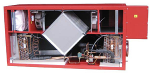
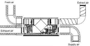
The airflow around our house was designed to use this device, so it quickly became apparent that it was something we needed to investigate further. A number of searches and phone calls later, finding someone who could service it in Scotland was proving tricky. When we did, it was followed up with ‘spares are difficult to get and it’s now an obsolete model; we can’t promise anything’.
The initial assessment of the unit quickly identified that a power transformer had broken and at least one of the fan units wasn’t working. Options at this point were to see if we could fix it, or look for an alternative. With costs of a replacement device in the region of £10,000 it was worth some time and effort to see what could be done with it and so this journey starts. It’s already non-functional so we can’t make it any less useful.
Basic Principles
Searching for the unit on the manufacturers website returned no results - why do compaines do this? Just because you’ve released a new model doesn’t mean you have to purge everything related to older ones. More general searching and we found schematics of the original circuit board and PDF copies of the installation manuals. At least we could then start trying to figure out how this device was supposed to work.

Problems
Looking at what was in front of us, the unit had at least one failed fan and the transformer was burnt out. The company that had come out to look at it confirmed the heat pump setup looked intact, and checked that it had refrigerant present. So really, it was mainly the electrical and control side of thing that wasn’t working.
Fans were discontinued units, as was the transformer. Chances of the control PCB working when there is clearly electrical failures was minimal and even if it did, was that the root cause of the failiure and would you ever trust it? Spares were not available from the manufacturer either. Now clear why the previous occupants had gone to lengths to state it was non-functional when the house was sold.
Control Board Analysis
So what does the controller do? Looking at the schematic we found, it seems to monitor some sensors and then control the heat pump and also the speeds of the fans. This latter item was performed by using a set of relays which would combine voltages from the multi-tap transformer. Vary the voltage into the fan and you control the speed. Looking at the schematic though, and if one of a number of the relays didn’t open or close properly, then the transformer would short out; which was probably the issue - a sticky relay. For the heat pump side, some of the relays control the compressor and a couple of solenoid valves. One to initiate a defrost cycle, the other to switch the function from heating the incoming air to cooling it. Let’s stop and think for a second; this is Scotland. Air conditioning is normally done by opening a window or a door and then closing it 30 seconds later as it’s now too cold. File that one in the ‘Nice to have’ column then.
The Plan
After this assessment, it was back to internet searching to see what options we could find for the broken components.
=> Fans
Although obsolete, the same manufacturer had a similar sized model, but with the extra features of speed control and a tachometer (rpm) output. No need for a multi-tap transformer or odd voltage combining relay circuits to change speeds.
=> Control Board
We do need some relays; the solenoid valves and compressor are mains AC powered so need switched on and off. We also need to monitor some sensors and probably add some more so we can see what’s going on without having to open things up all the time. A Raspberry Pi or even a small microcontroller board would be sufficient. Low voltage and easy to hook up to the network so telemetry can be reported.
=> Transformer
The new fans run from mains voltage along with the solenoids and compressor, so the only transformer requirement is for the control board power which is going to be 5V or 12V at most. Much easier and cheaper; no complex multi-tap transformer to find.
=> Software
The control board was going to need some software development to monitor report and control the various elements, but this was probably the least of our worries. The fans needed ordered first so we could see how they really worked, as datasheets are great to a point.
Next Steps
With items ordered and datasheets collected, it’s time to wait for parcels to arrive and then some lab/bench testing, before work on a final solution could continue. In the interim, we managed to switch the single working fan to the ’extract’ side of the unit and feed it with a spare 120VAC transformer that we had from doing some work with US voltage kit. The house had some air movement again, albeit extract only and no (or at least very minimal) heat recovery. We did try running the fan with full 240VAC, but it was noisy and created a draught! Half speed fans were much quieter and had a less obvious effect on house temperatures.
Links
Index
Part 1 | Part 2